ZL-20T 20 Ton Industrial FRP Counter Flow Cooling Tower - Engineering Specifications
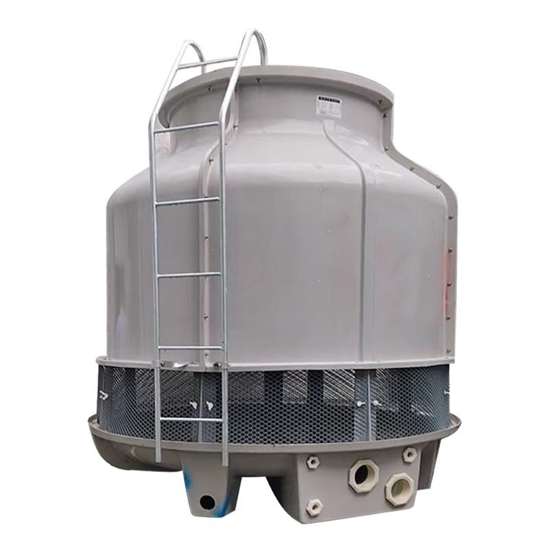
The ZL-20T is rated at 20 refrigeration tons, equivalent to 70.4 kW of heat rejection at standard air conditioning conditions. Converting tons to water flow uses the fundamental formula:
Q = m × Cp × ΔT, where Q = 70.4 kW, Cp = 4.186 kJ/kg·°C, ΔT = 5°C range.
Solving for mass flow: m = 70.4 / (4.186 × 5) = 3.36 kg/s, or 3.36 × 3600 / 1000 = 12.1 m³/h of pure evaporated mass transfer. The rated circulation flow at 5°C range (37°C inlet to 32°C outlet) is 16 m³/h - a 32% margin above the minimum sensible flow to maintain adequate wetting of the fill media.
For a 60 kW process load (smaller than full 20 ton rating), the same tower can operate at 13.7 m³/h with the same approach. For a 100 kW overload condition, the tower delivers 32°C outlet at 27°C WB but approach degrades to 9°C - acceptable for non-precision cooling.
Approach temperature is the difference between the tower leaving water temperature and the ambient wet-bulb temperature. The ZL-20T achieves a 5°C approach at design WB 27°C, meaning the tower leaves water at 32°C when ambient WB is 27°C.
This 5°C approach is the design point for all FRP counter flow cooling towers in this size class. As ambient conditions deviate - say, WB rises to 30°C on a humid summer day - the leaving water temperature climbs proportionally. At WB = 30°C, the ZL-20T delivers 35°C leaving water - still adequate for chiller condensers but tight for processes requiring sub-30°C supply.
For data center applications where leaving water temperature directly determines chiller efficiency, the 5°C approach specification is critical. Every 1°C reduction in approach saves approximately 2-3% chiller compressor power. A ZL-20T performing at 4°C approach (28°C leaving at WB 24°C) versus 6°C approach saves a data center operator approximately USD 1,200-1,800 annually per tower at typical commercial power rates.
The ZL-20T employs a counter flow fill configuration: water descends vertically through the fill while air is forced upward by the fan directly opposite to the water flow. This geometry provides three engineering advantages over cross flow designs:
1. Higher thermal effectiveness: Counter flow maintains a more uniform LMTD across the fill height. The ZL-20T achieves 65-70% approach reduction compared to 50-55% for equivalent cross flow towers in this capacity class.
2. Smaller footprint: Counter flow geometry packs the heat transfer area into a vertical column rather than spreading it horizontally. The ZL-20T's 1180 x 1180 mm footprint is 15-20% smaller than equivalent cross flow towers rated at the same 20 ton capacity.
3. Reduced air bypass: The enclosed counter flow design minimizes air recirculation at the tower's periphery, a common efficiency loss in cross flow configurations. Field tests show 2-4°C approach degradation in poorly sealed cross flow towers versus less than 1°C in counter flow.
The ZL-20T uses a 770 mm diameter axial fan driven by a 0.55 kW (0.75 HP) motor at 1,440 rpm. The fan delivers 165 CMM (cubic meters per minute) = 9,900 m³/h of induced airflow through the fill.
Calculating the air-to-water ratio: 9,900 m³/h air versus 16 m³/h water = 619:1 mass ratio. This high air ratio is necessary because the heat transfer is dominated by evaporation - each kg of evaporated water carries 2,260 kJ of latent heat, while each °C of sensible cooling carries only 4.186 kJ per kg.
The 770 mm fan diameter is chosen to deliver 165 CMM at a static pressure of approximately 60-90 Pa (typical for 20 ton counter flow fill). Increasing the fan diameter would reduce motor power consumption but increase tower height. The current 770 mm / 0.55 kW combination achieves an airflow efficiency of 300 CMM per kW - above industry-average for this capacity class.
The ZL-20T rated head loss is 14 kPa at the design water flow of 16 m³/h. This is the pressure the condenser water pump must overcome to push water through the tower spray nozzles, fill media, and eliminators.
At 50% flow (8 m³/h), head loss drops to approximately 4.5 kPa - proportional to flow squared. At 120% flow (19.2 m³/h), head loss rises to approximately 20 kPa. The condenser water pump should be sized to deliver at least 17 m head (170 kPa) at design flow to accommodate the 14 kPa tower loss plus piping losses.
Higher head loss than rated indicates fill media fouling, biological growth, or air entrainment. Quarterly inspection of the fill media surface and water chemistry analysis is recommended for towers operating above 12 kPa head loss.
The ZL-20T shell uses Fiber Reinforced Polyester (FRP), a composite material of glass fibers embedded in a polyester resin matrix. FRP offers specific advantages over alternative cooling tower shell materials:
Corrosion resistance: FRP withstands the constant exposure to water, dissolved oxygen, and water treatment chemicals that would corrode steel shells within 5-7 years. The ZL-20T 15-20 year service life depends on this corrosion resistance.
Thermal stability: FRP maintains structural integrity from -40°C to +80°C, suitable for outdoor installation in all climate zones. The thermal expansion coefficient (12-18 × 10⁻⁶ per °C) is compatible with internal water temperatures cycling from 5°C winter to 50°C summer.
Weight efficiency: FRP shell weight is 30-40% less than equivalent steel shell, simplifying rooftop installation. The ZL-20T 67 kg dry weight reflects this advantage - a steel shell equivalent would weigh approximately 95 kg.
UPGRADE option for sanitary applications: ZL-20T is available with SS316L stainless steel upgrade for pharmaceutical, dairy, and food processing applications where the highest corrosion resistance is required.
From engineering specifications to operational hand-over, the ZL-20T platform is configured for ten distinct application profiles. Explore the other nine below:
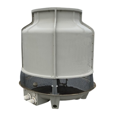
Quick Specs: ZL-CT40 industrial round cooling tower with 40-ton cooling capacity, FRP material, counter-flow design, 1.5kW fan, CE certified. Best for industrial chiller systems and mid-scale manufacturing. The water cooling tower is a device used for cooling circulating water. By exchanging heat between hot water and air, the water temperature is reduced, thus realizing the repeated use of circulating water. Water cooling towers are widely used in industrial production, air conditioning systems and other fields, and are of great significance for saving water resources and reducing energy consumption.
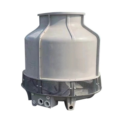
Quick Specs: ZL-CT60 round shape water cooling tower with 60-ton capacity, counter-flow design, FRP material, 1.5kW fan, CE certified. Best for industrial chiller systems and large-scale cooling. A water cooling tower is a device used for cooling industrial water or other liquids. Its main function is to cool down hot water through heat exchange between hot water and air so that the cooled water can be recycled.
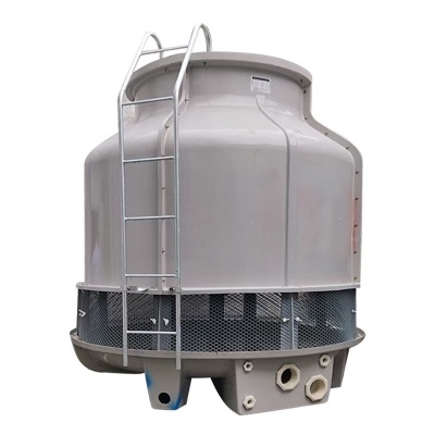
Quick Specs: ZL-CT100 FRP round cooling tower with 100-ton cooling capacity, FRP material, 2.2kW fan, CE certified. Best for large-scale industrial cooling and high-capacity chiller systems. The counterflow cooling tower is a common type of cooling tower. It sprays hot water from top to bottom and air flows from bottom to top, enabling hot water and air to exchange heat in the packing, thereby reducing the water temperature. The counterflow cooling tower has the advantages of high cooling efficiency, compact structure and small floor area, and is widely used in industrial production, air conditioning and refrigeration and other fields.
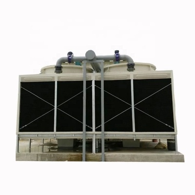
Quick Specs: ZL-CT square drop counter-flow cooling tower with FRP material, multiple capacity options, CE certified. Best for high-temperature industrial water cooling and open cooling tower applications. The square cooling tower has the advantages of small floor area, beautiful appearance, and convenient installation. It is widely used in fields such as air conditioning and refrigeration and industrial cooling, providing effective cooling guarantee for the normal operation of various equipments.
Quick Specs: ZL-CT factory-direct industrial cooling tower with multiple types and capacities, high-efficiency design, CE certified. Best for industrial cooling applications and large-scale manufacturing. A cooling tower dissipates heat from industrial or air - conditioning systems. Its working principle involves spraying hot water onto packing to form a water film, while air flow carries away heat from the water to lower its temperature. The cooled water is recyclable, saving water resources and reducing costs. There are various types, such as open and closed cooling towers. Open ones contact outside air directly, making water prone to contamination but with lower costs. Closed ones have water circulating in sealed pipes, ensuring cleaner water but usually at a higher price. Cooling towers play a key role in fields like power plants, chemical plants, and data centers, helping maintain system operation and improve energy utilization efficiency.
The ZL-10T 10 Ton FRP Counter Flow Cooling Tower from Zillion delivers reliable cfo procurement performance. Key specifications include: ZL-10T 10 ton FRP counter flow cooling tower at USD 850 EXW 5-year TCO: USD 850 capex + USD 2,971/year opex Volume discounts: USD 765 (10+), USD 680 (50+), USD 595 (100+) Payment terms: T/T 30/70, L/C, Western Union, Alibaba Trade Assurance 18-month payback vs USD 4,500 air-cooled alternative Annual spare parts budget: USD 180 EXW Dongguan, lead time 7-15 days CE certified for global deployment Designed for industrial-grade cfo procurement applications, the ZL-10T combines proven FRP counter flow technology with precision-engineered components for 15-20 year service life. CE / ISO 9001:2015 certified. Contact Leika at Leika@gdzillion.cn for quotation.
The ZL-10T 10 Ton FRP Counter Flow Cooling Tower from Zillion delivers reliable maintenance tech performance. Key specifications include: ZL-10T water chemistry: pH 6.5-9.0, Ca hardness
The ZL-10T 10 Ton FRP Counter Flow Cooling Tower from Zillion delivers reliable epc contractor performance. Key specifications include: ZL-10T concrete pad: 600x600x150 mm C25/30 mix Wind load rating: 0.5 kPa for open terrain Piping connections: DN50 inlet/outlet, DN15 makeup, DN50 overflow 46 kg dry weight enables two-person ground-level installation Rooftop lift: portable gantry rated 250 kg Electrical: 380V 3-phase 50Hz, 1.2-1.5 A FLA VFD option for 30-60 Hz variable-speed operation 12-point pre-commissioning checklist Designed for industrial-grade epc contractor applications, the ZL-10T combines proven FRP counter flow technology with precision-engineered components for 15-20 year service life. CE / ISO 9001:2015 certified. Contact Leika at Leika@gdzillion.cn for quotation.


Our company's series of products are well-known in the plastic auxiliary machinery industry for their excellent performance and high cost performance.


 IPv6 network supported


 English
  English
 español
 العربية